Magnetostrictive Transducer - HMT
An electric impulse is produced in the headpipe and creates a circular magnetic field. The permanent magnet related to the object to be measured is the sensor. The lines of the magnetic field of the permanent magnet are in a 900 angel with the ones produced by impulse of the electric current. The interaction of the magnetic fields causes a flexible deformation (magnetostriction) in the waveguide. This deformation spreads to either ends in the waveguide. The propagation speed reaches 2,850 m/sec. The mechanical impulse is absorbed at one end of the waveguide and changed at the other end into an electrical signal, by reversal of the magnetostrictive effect. A controller calculates the travel speed of the impulse which is proportional to the displacement.
This principle enables a contactless, wear-free and absolute measurement. The sensors operate reliably in hydraulic cylinders, machine tools, presses, woodworking machines, rolling systems, packaging machines, portal robot, cutting machines, in the mining industry and in the conveying engineering.
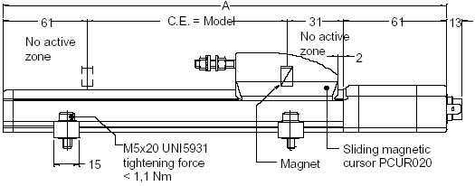
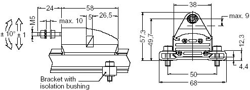
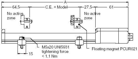
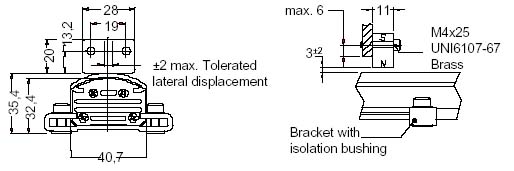
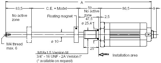
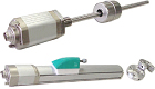
There are two different type of magnetostrictive sensors. The series of HMTW is used in the automated measuring technique for the position and distance measurement. The object to be measured is connected thereby with the sliding cursor or the floating magnet. By the different installation possibilities these sensors are suitable for a multiplicity of applications. The series of HMTZ is conceived for the installation in hydraulic cylinders. The ring permanent magnet move along a rod without any contact. The different execution of the ring magnets permits a simple installation in hydraulic systems. The sensors can be installed in systems with pressure up to 350 bar (overpressure 700 bar).
Technical data
Ranges
100/130/150/200/225/300/400/450/500/600/700/750/800/900/1000/1250/1500/1750/2000/2250/2750/3000/3250/3500/3750/4000
Output
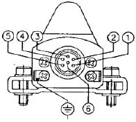
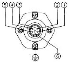
0...10 VDC / 4...20 mA, 0...20 mA and inv. signal, Start/Stop (RS422 compatible), PWM, SSI (RS422/485), CANopen (DS-301), load (analog) > 5 kW.
Update time
< 1ms for analog output (length depending)
Scanning rate for position
CANopen - from 1 to 4 ms, SSI - from 0.5 to 3 ms
Linearity
Range 100 mm - +/- 0.03 %; Range from 130 mm to 150 mm - +/- 0.025 %; Range above: +/- 0.02 %.
Repeatability
+/- 0.001 % of the electrical stroke (C. E. )
Hysteresis
< 0.01 mm
Resolution
< 0.1 mV or < 0.2 mA (analog), 0.1 mm (digital), 5 mm CANopen (2 mm on request), 5/10/20/40 mm SSI (2 mm on request)
Power supply
24 VDC +/- 20 %, ripple 1 Vpp max., consumption 100 mA max., protection against polarity inversion.
Type of magnet
Sliding cursor for HMTW, floating magnet for HMTW, Ring magnet for HMTZ
Protection
IP 67
Displacement speed
< 10 m/s
Force required to move the sliding cursor
< 1 N, max. acceleration < 100 m/s2
Temperature stability
< 0.01 % MB / 0C
Temperature
Working - -40...+70 0C, storage - -40...+100 0C
Shock test
100 g / 11 ms (IEC68T2-27)
Vibration
12 g / 10...2,000 Hz (IEC68T2-6)
Max. length A
Range + 153 for model HMTW, Range + 200 for model HMTZ.